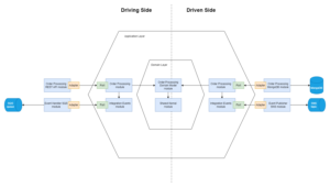
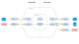
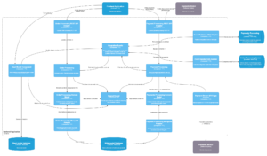
Modular monolith, CQRS, DDD. So many buzzwords in one phrase. Most likely you have already read about them. Maybe you had a chance to work with some of them. But have you ever tried to put all of them together into a single application? Each of those concepts individually is quite easy to grasp. Although implementing all of them together into a single application might require some thinking. Let’s put our thinking hats on and see how to structure your code in a modular monolith application with CQRS and DDD.
1. Outline
This article is the first part of a series of articles dedicated to structuring the code of modular monolith with CQRS and DDD. The series consists of :
- Part 1 – Understanding example domain & designing architecture
- Part 2 – Implementing modular monolith using Spring Modulith
- Part 3 – Implementing modular monolith using Maven modules
- Part 4 – Comparison, trade-offs and conclusions
2. Key concepts
Before we proceed to design and implementation, it is important to first understand the 3 patterns that we are going to use. Each of the patterns deserves a separate article on its own. However, the main focus of this article is how to implement them – hence here you will only find a brief description with the most crucial aspects highlighted.
2.1. Modular monolith
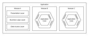
A modular monolith is an architectural pattern that structures application into modules. This pattern promotes high cohesion and loose coupling of modules. To achieve this, modules:
- must be independent and interchangeable and
- must have everything necessary to provide desired functionality and
- must have defined interface
Want to know more? Read Microservices Killer: Modular Monolithic Architecture.
2.2. CQRS
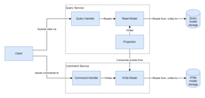
CQRS, or Command Query Responsibility Segregation, is an architectural pattern that separates the responsibilities for reading and writing data in a software system. It involves maintaining separate models for read and write operations, allowing for optimized performance, scalability, and flexibility in handling complex data workflows.
As part of CQRS pattern there is write side with Command Handlers and read side with Query Handlers. Command Handlers handle commands and Query Handlers handle queries. Handling commands involves modifying write model. Handling queries involves reading data from query model and returning data to caller. There also has to be something that propagates changes of data in write model to data in read model. This can be either done at database-level or application-level.
Want to know more? Read CQRS by Martin Fowler.
2.3. DDD
DDD, or Domain-Driven Design, is an approach to software development that focuses on understanding and modeling complex business domains. It emphasizes collaboration between domain experts and developers to create a shared understanding of the problem space, resulting in well-designed, maintainable software systems aligned with business requirements.
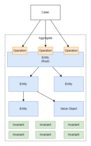
One key aspect of DDD that I want to highlight is that there is the concept of an aggregate. As part of developing a DDD-style application, we define a domain model. Aggregate is a key building block of the domain model. Aggregate is a cluster of domain objects (entities and value objects). Aggregate has one root entity. Only the root entity exposes operations that can be executed to modify the aggregate. The rest of the entities cannot be modified directly from outside the aggregate. Aggregate protects business rules (invariants). Its state has to remain consistent with protected business rules at all times. When persisting aggregate to transactional storage you persist the entire aggregate in a transaction. This means that the aggregate is transactionally consistent.
Another key concept of DDD is bounded context. A Bounded Context is a logical boundary of a domain where particular terms and rules apply consistently. Inside this boundary, all terms, definitions, and concepts form the Ubiquitous Language. To give you an example – consider Product entity in E-Commerce platform. As part of Shipping bounded context, the Product entity might have properties such as weight, height, length, or depth. As part of Sales context, those properties are not relevant and Product might be defined differently.
Want to know more? Read Domain-Driven Design Quickly by InfoQ.
3. Example domain
Before we proceed to designing the architecture – first we need to understand business processes that our system will support. The domain is e-commerce. The business process that you will see below is just a slice of a much larger domain. Moreover, it’s a very simplistic idea of what might be going on in the real world e-commerce system. The important part is that it gives us a good base to showcase how to build similar solutions.
Below you can find a diagram showing our example business process.
As part of our example business process, there is a customer. The customer orders products and makes payments for the orders. Payments are made via a payment broker which is an external system. Once the customer starts a payment, then he’s redirected to the payment broker site where he/she makes the payment. The depicted flow of events shows only the “happy path”. Cases like unsuccessful payment or order canceling were skipped to keep the example simple.
4. Architecture design
So, are we ready to start implementing our application?… no, not yet. We don’t know what the responsibilities of the application will be. What integrations will it have? Will this application contain a user interface? What will we use for storage? What application-level architecture will we use? Answering those and more questions will influence what modules we’ll create while implementing our modular monolith.
4.1. Motivation
Why did we choose modular monolith, CQRS, and DDD in the first place?
In real-world projects, architecture design emerges from functional requirements, non-functional requirements, different types of constraints, etc. Those factors influence the decisions of software architects. They make them select particular architectural patterns, technical stacks, and so on. In case of this article, the project is more academic, there are no real stakeholders – hence reasons that made us choose the 3 patterns are also made up.
Nevertheless, it is important to understand these motivations as they affect the way we design architecture. Let’s define them and let’s make them as close to real-world cases as possible. Our motivations are:
- We decided to start with a modular monolith to deffer the complexity and development overhead that comes with distributed architecture, but the intent is to split the monolith into microservices in the future.
- We decided to implement CQRS pattern to improve the performance of read and write operations. We justify the added complexity with the prediction that in the future we will need to scale resources for read and write operations independently.
- We decided to code in DDD-style because we assessed that the domain that we’re dealing with is complex with a lot of business rules and we want to keep our implementation adequate to problems being solved while assuring high quality and performance.
The target now is to identify modules of our modular monolith. Let’s design system-level and application-level architecture to identify boundaries, responsibilities, dependencies, and by extension – the modules that we crave so much.
4.2. Design-Level Event Storming
A good way to start designing a DDD-style system is running a Design-Level Event Storming session. It helps you identify screens that should be displayed to end users, read models, integrations with external systems, and DDD aggregates that the system will be built of.
Executing an Event Storming session is outside the scope of this article. Nevertheless, below you can find a diagram showing the results of running Design-Level Event Storming for our example domain.
There are some things to notice in the diagram above that are important from a DDD point of view. We identified:
- 2 aggragates – Order and Payment
- many commands and domain events associated with aggregates
- 2 bounded contexts – Order Processing and Payment Processing
- 1 external system – Payment Broker
Also, there are things to notice that are important from CQRS point of view. We identified:
- 2 read models: Payments read model and Orders read model
- 2 write models: Order aggregate and Payment aggregate
4.3. Context-level architecture
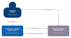
We are going to draw architecture diagrams in the C4 model. It is a good idea to start with a System Context diagram. It’ll show us the boundaries of the system that we are designing, its main use cases and dependencies. You can find the diagram below.
The context of a designed system is quite simple. There is 1 person, 1 software system, and 1 external software system. The software system that we’ll be implementing is the E-Commerce System. The Payment Broker software system is the external one. Also, this is the one that we identified in the section explaining the domain.
4.4. System-level architecture
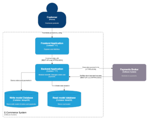
OK, so we know what the context of the E-Commerce System is. We are getting closer to the good stuff. Now we need to determine what applications the designed system will consist of. We already know that there will be a modular monolith, but there might also be others. By doing so, we can determine what responsibilities belong to other applications rather than to our modular monolith. Additionally, we need to find what the relationships will be of the identified applications. Knowing the dependencies of the monolith will affect its internal structure. Let’s take a look at the Containers Diagram.
In the center, there is a Backend Application. This is our modular monolith. You can also see that we decided to have a separate Frontend Application. The Backend Application will expose REST API endpoints for communication from the Frontend Application. You can also notice that communication between the Backend Application and Payment Broker will be synchronous and over HTTP. There are separate storages for the read model and write model, and we have already selected backing technologies to be MongoDB (NoSQL storage) for the write model and MariaDB (relational database) for the read model. The technical stack of the backend application is not yet specified. This is intentional. We’ll decide on it in the second part of the article.
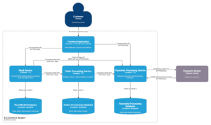
Now let’s try to anticipate how this Containers Diagram will change in the future when backend architecture will change to microservices. This will help us design modules of a modular monolith. Take a look at the diagram below.
The Backend Application will be split into 3 microservices.
Let’s assess this architecture from a CQRS point of view. Order Processing Service and Payment Processing Service are command services and Read Service is a query service. Our intent to be able to scale read and write services independently is satisfied.
Let’s assess this architecture from a DDD point of view. Order Processing Service and Payment Processing Service are named after bounded contexts. Dividing microservices by bounded contexts is not the only way to do it. Although as part of our example let’s assume that we’ll take this approach because we want to limit the amount of cases where a change request from a single stakeholder will require a change of more than 1 backend service.
4.5. Application-level architecture
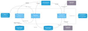
Now, it’s time to identify modules of our Backend Application. The first thing we can do is name 3 modules that we intend to extract into 3 separate microservices. They will provide the same functionalities as intended microservices and will be named appropriately. Let’s take a look at the Component Diagram below.
There are 3 components (modules) in the diagram. Read Model, Order Processing, and Payment Processing. You probably noticed that we have not defined the technical details of what those components are. This is intentional and related to not having a technical stack for the application. We will make those decisions in the next part of the article.
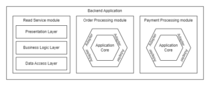
Ok, but what will be the internal architecture of each microservice after we split the monolith? Well, unless we change it, it will be whatever we will code inside of the 3 modules from the beginning. It is a good idea to make this design decision upfront. As we stated earlier in the article – each module of a modular monolith can have a different internal architecture.
We decided to keep the Read Model module simple – hence we selected a 3-layer architecture for it. On the other hand Order Processing module and Payment Processing module will be complex and written in DDD-style – hence we selected hexagonal architecture for them.
Now, let’s see what sub-modules we will identify in hexagon-based modules.
In the case of the Order Processing module, we identified:
- the Order Processing Domain Model sub-module in the domain layer,
- the Order Processing sub-module in the application layer,
- the Order Processing REST API and Order Processing MongoDB sub-modules in the adapters layer.
In the case of Payment Processing module, we identified:
- the Payment Processing Domain Model sub-module in the domain layer.
- the Payment Processing sub-module in the application layer
- the Payment Processing REST API and Payment Processing MongoDB sub-modules in the adapters layer.
- the Shared Kernel sub-module in the domain layer,
- the Integration Events sub-module in the application layer,
- the Event Handler SQS and Event Publisher SNS sub-modules in the adapters layer.
The resulting level of granularity of modules is sufficient to start implementation. We identified 3 main modules and we split them into sub-modules keeping in mind that the intent is to extract microservices from monolith in the future. Splitting the Read Service module would not add much value at this point as it is going to be quite simple.
5. Summary
In this first part of the article, we’ve explained Modular monolith, CQRS, and DDD concepts. We explored an example domain that the solution developed as part of this article will be based on. We identified DDD aggregates and bounded contexts. We identified CQRS read models and write models. We stated what is our motivation for implementing modular monolith with CQRS in DDD-style. With that motivation in mind, we designed system-level and application-level architecture.
5.1. What's next?...
The next step will be implementing what we designed. In part 2 of the article, we will implement the application in Java using Spring Boot framework with Spring Modulith module.

